Severity: 8192
Message: Function mcrypt_get_iv_size() is deprecated
Filename: libraries/Encrypt.php
Line Number: 319
Severity: 8192
Message: Function mcrypt_create_iv() is deprecated
Filename: libraries/Encrypt.php
Line Number: 320
Severity: 8192
Message: Function mcrypt_encrypt() is deprecated
Filename: libraries/Encrypt.php
Line Number: 321
Severity: 8192
Message: Function mcrypt_get_iv_size() is deprecated
Filename: libraries/Encrypt.php
Line Number: 319
Severity: 8192
Message: Function mcrypt_create_iv() is deprecated
Filename: libraries/Encrypt.php
Line Number: 320
Severity: 8192
Message: Function mcrypt_encrypt() is deprecated
Filename: libraries/Encrypt.php
Line Number: 321
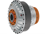
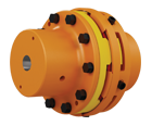
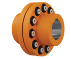
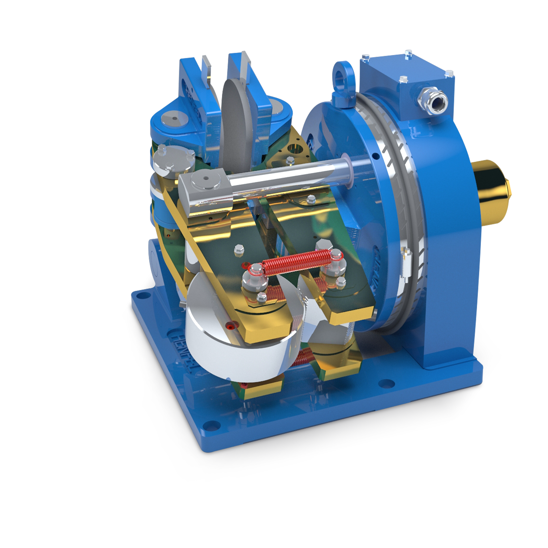
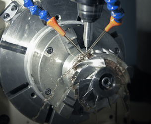
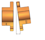
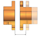
With flexible elements which make them torsionally elastic, the Flexible Couplings Henflex HXP may have a wide range of applications where reliable torque transmission is required. Due to a careful selection of materials, it can be used on equipments with both high and low rotation
The flexible elements are assembled axially, and they allow operation with radial, axial and angular misalignments. Besides, it absorbs shocks and vibrations from both drive and driven machines..
Its pins are over dimensioned in order to withstand many times the shear load descendant from the maximum allowed shock, which grants reliability and long life spam to these components.
Due to its constructive form, these couplings may be applied on both rotation directions and be submitted to rotation reversions without any consequence to its operational conditions.
Besides requiring low maintenance, these couplings do not require lubrication and therefore, its environmental impact is null. If all assembly guidelines are followed, the flexible pins and elastic elements will have a long lifespan.
The Henflex HXP line is available in many sizes and covers operating torques ranging from 200 to 1.300.000 Nm and shafts of up to Ø600 mm.
In order to dimension the HXP flexible couplings for continuous operation regimen, you should first obtain the operation torque (T0 ), which is found by: 0 ), which is found by:
T0 = C x P ⁄ nm where:
T0 = System operational torque [Nm];
P = Input power [kW or HP];
nm = Rotation speed [rpm];
C:
C = 9550 for P in kW;
C = 7030 for P in HP;
Once you find the operational torque, you can obtain thecoupling’s nominal torque which is found by: (T na ) which is found by:
Tna ≥ T0 x f1
Where:
Tna = Coupling’s nominal torque
f1 = Service factor
Important remark: These couplings were dimensioned to withstand start up and braking at a maximum torque of up to three times the nominal torque of the coupling. These operations can be repeated 25 times per hour. However, should the coupling be submitted to loads involving shocks, the following equation must be considered:
T na max = Coupling’s maximum torque;
Ts = Maximum impact torque of the system.
The service factor is a number obtained empirically that takes into account the operating regimes of the driving and driven machines. The table bellow indicates the service factor considering the driven machine regimen and the drive type. In order to simplify the service conditions they were divided into three groups:
The selection methods presented above are only valid if the environmental temperature where the coupling is applied ranges between -30ºC and 80ºC, with assembling and alignment as per catalogue and manual instructions, with no more than 25 start ups per hour
For tougher applications or if you have any questions, please contact our engineering department.
It’s also important to consider the shaft dimensions of the drive and driven machines as well as the admissible rotation speed of the couplings.
|
Service factor for daily operations of up to 24 hours |
||||
|
Types of loads * |
Drive |
|||
|
Electric Motor |
Internal combustion motor with 4 to 6 cylinders |
Internal combustion motor with one to 3 cylinders |
||
|
Uniform load |
Ventilators P/n=0,1 Centrifugal pumps (low viscosity) Screw pumps |
1.0 |
1.25 |
1.75 |
|
Shocks Medium |
Exaustores e ventilators P/n >0,1 Conveyor belts and chains Bucket elevators Winches Shakers, centrifuges and mixers Concrete mixers Washing machines Woods machines Calenders, extruders and plastic mixers Machines rotary tool Folding sheets Propellers sea Furnaces and rotary cylinders |
1.25 |
1.5 |
2.0 |
|
Shocks Strong |
Generators and transformers Piston pumps Mills generally Crushers Drums and rotary mills Machines for paper and pulp Cranes Bucket wheel Presses, hammers and shears Rolling mills and extruders metals Mixers and rubber extruders Elevators |
1.75 |
2.0 |
2.5 |
(*) For other equipments, please consult our engineering application and technical sales department.
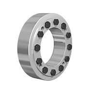
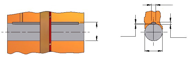
HXP flexible couplings are set on the shaft with a parallel feather key in accordance with the DIN 6885 standard, sheet 1.
|
Parallel feather key – DIN 6885/1 |
|||||
|
Diameter d |
Width b(*) |
Height h |
Keyway depth on the shaft t1 |
Keyway depth on the hub d + t2 |
|
|
Above of (mm) |
Until (mm) |
(mm) |
(mm) |
(mm) |
(mm) |
|
8 |
10 |
3 |
3 |
1,8 |
d+ 1,4 |
|
10 |
12 |
4 |
4 |
2,5 |
d+ 1,8 |
|
12 |
17 |
5 |
5 |
3 |
d+ 2,3 |
|
17 |
22 |
6 |
6 |
3,5 |
d+ 2,8 |
|
22 |
30 |
8 |
7 |
4 |
d+ 3,3 |
|
30 |
38 |
10 |
8 |
5 |
d+ 3,3 |
|
38 |
44 |
12 |
8 |
5 |
d+ 3,3 |
|
44 |
50 |
14 |
9 |
5,5 |
d+ 3,8 |
|
50 |
58 |
16 |
10 |
6 |
d+ 4,3 |
|
58 |
65 |
18 |
11 |
7 |
d+ 4,4 |
|
65 |
75 |
20 |
12 |
7,5 |
d+ 4,9 |
|
75 |
85 |
22 |
14 |
9 |
d+ 5,4 |
|
85 |
95 |
25 |
14 |
9 |
d+ 5,4 |
|
95 |
110 |
28 |
16 |
10 |
d+ 6,4 |
|
110 |
130 |
32 |
18 |
11 |
d+ 7,4 |
|
130 |
150 |
36 |
20 |
12 |
d+ 8,4 |
|
150 |
170 |
40 |
22 |
13 |
d+ 9,4 |
|
170 |
200 |
45 |
25 |
15 |
d+10,4 |
|
200 |
230 |
50 |
28 |
17 |
d+11,4 |
|
230 |
260 |
56 |
32 |
20 |
d+12,4 |
|
260 |
290 |
63 |
32 |
20 |
d+12,4 |
|
290 |
330 |
70 |
36 |
22 |
d+14,4 |
|
330 |
380 |
80 |
40 |
25 |
d+15,4 |
|
380 |
440 |
90 |
45 |
28 |
d+17,4 |
|
440 |
500 |
100 |
50 |
31 |
d+19,4 |
(*) The tolerance zone for the width “b” of the hub keyway is in accordance with the norms ISO JS9 or ISO P9 for severe operation conditions. (Eg. Loaded reversion)
|
Type |
Material |
Hardness |
Temperature range |
Selection criteria |
Field of application |
|
Pattern |
Perbunan Black |
80 Shore |
From -30 °C To +80 °C |
Every actuation application in engineering field mechanical |
|
|
Special type request |
Perbunan Black |
60 Shore* |
From -30 °C To +80 °C |
hange speed resonance by changing the dynamic torsional stiffness |
|
|
Natural rubber Black |
80 Shore |
From -50 °C To +50 °C |
Change the temperature range for use in low temperature. |
||
|
Perbunan Green |
80 Shore |
From -30 °C To +80 °C |
Electrical insulator |
*Torque reduction due to hardness must be considered
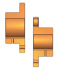
The misalignment of the components can affect the performance of the coupling due to vibrations, temperatures and noises, to name a few problems, and reduce the life span of the flexible elements and driven machines. Both radial and axial misalignment of the shaft tips must be minimum in order to increase the life span of elastic elements. The assembly must be done in accordance with the instructions in the catalogue and obey the spacing and tolerances.

|
Size |
Spacing adjustment during assembly |
Shaft spacing (round numbers) for radial, angular and axial allowed misalignments during assembly |
||||||||
|
d a> |
L1 min. |
L1 máx. |
Speed 500 min -1 |
Speed 1000 min -1 |
Speed 1500 min -1 |
Speed 3000 min -1 |
||||
|
in |
mm |
mm* |
Grau* |
mm* |
Grau* |
mm* |
Grau* |
mm* |
Grau* |
|
|
4 |
2 |
4 |
0,35 |
0,20 |
0,25 |
0,14 |
0,20 |
0,11 |
0,15 |
0,08 |
|
5 |
2 |
4 |
0,40 |
0,18 |
0,30 |
1,13 |
0,25 |
0,11 |
0,15 |
0,07 |
|
5,5 |
2 |
4 |
0,45 |
0,18 |
0,30 |
1,12 |
0,25 |
0,10 |
0,20 |
0,07 |
|
6 |
2 |
5 |
0,45 |
0,17 |
0,35 |
1,12 |
0,25 |
0,10 |
0,20 |
0,07 |
|
7 |
2 |
5 |
0,50 |
0,16 |
0,35 |
0,11 |
0,30 |
0,09 |
0,20 |
0,06 |
|
8 |
2 |
5 |
0,50 |
0,15 |
0,40 |
0,11 |
0,30 |
0,09 |
0,20 |
0,06 |
|
9 |
2 |
5 |
0,60 |
0,15 |
0,40 |
0,10 |
0,35 |
0,09 |
0,25 |
0,06 |
|
10 |
2 |
5 |
0,65 |
0,14 |
0,45 |
0,10 |
0,35 |
0,08 |
0,25 |
0,06 |
|
11 |
3 |
6 |
0,70 |
0,14 |
0,50 |
0,10 |
0,40 |
0,08 |
0,30 |
0,06 |
|
13 |
3 |
6 |
0,75 |
0,13 |
0,55 |
0,09 |
0,45 |
0,08 |
0,30 |
0,06 |
|
14 |
3 |
6 |
0,80 |
0,13 |
0,60 |
0,09 |
0,50 |
0,08 |
0,35 |
0,05 |
|
16 |
3 |
6 |
0,90 |
0,13 |
0,65 |
0,09 |
0,50 |
0,07 |
||
|
18 |
4 |
7 |
1,00 |
0,12 |
0,70 |
0,09 |
0,55 |
0,07 |
||
|
20 |
4 |
7 |
1,10 |
0,12 |
0,75 |
0,09 |
0,60 |
0,07 |
||
|
22 |
4 |
8 |
1,20 |
0,12 |
0,85 |
0,08 |
0,70 |
0,07 |
||
|
25 |
4 |
8 |
1,30 |
0,12 |
0,90 |
0,08 |
0,75 |
0,07 |
||
|
28 |
5 |
9 |
1,45 |
0,12 |
1,00 |
0,08 |
0,85 |
0,07 |
||
|
31,5 |
5 |
9 |
1,60 |
0,12 |
1,10 |
0,08 |
||||
|
36 |
5 |
10 |
1,80 |
0,11 |
1,30 |
0,08 |
||||
|
40 |
5 |
10 |
2,00 |
0,11 |
1,40 |
0,08 |
||||
|
44 |
6 |
11 |
2,20 |
0,11 |
1,50 |
0,08 |
||||
|
49 |
6 |
11 |
2,40 |
0,11 |
||||||
|
55 |
6 |
12 |
2,70 |
0,11 |
||||||
|
63 |
6 |
12 |
3,00 |
0,11 |
||||||
|
71 |
8 |
16 |
3,40 |
0,11 |
||||||
|
79 |
8 |
16 |
3,80 |
0,11 |
||||||
mm* = Δ Ir perm, Δ L1 perm, Δla perm
Grau* = Δw perm
Radial, angular and axial allowed misalignments can be calculated with the following formula:
ΔIr perm = ΔL1 perm = ΔIa perm = ( 0,1 + da⁄39,37 ) x 40 ⁄√n
Where:
n = Coupling speed (min-1)
da = Coupling size(in)
ΔIr perm = Radial misalignment allowed (mm)
ΔL1 perm = Angular misalignment (mm)
ΔIa perm = Axial misalignment allowed (mm)
The hubs balancing of Henflex HXP couplings are in accordance with the NBR 8008 norm.
For n = 1500 RPM or peripheral speed = 30m/s, do the balancing on one plan with G16 quality.
For n> 1500 RPM or peripheral speed >30m/s, do the balancing on both plans with G6,3 quality.
The hubs are supplied balanced whenever the operational rotation informed is within the balancing region on the graph below:
Attention: Always check the admissible rotation on the dimensional table.