Severity: 8192
Message: Function mcrypt_get_iv_size() is deprecated
Filename: libraries/Encrypt.php
Line Number: 319
Severity: 8192
Message: Function mcrypt_create_iv() is deprecated
Filename: libraries/Encrypt.php
Line Number: 320
Severity: 8192
Message: Function mcrypt_encrypt() is deprecated
Filename: libraries/Encrypt.php
Line Number: 321
Severity: 8192
Message: Function mcrypt_get_iv_size() is deprecated
Filename: libraries/Encrypt.php
Line Number: 319
Severity: 8192
Message: Function mcrypt_create_iv() is deprecated
Filename: libraries/Encrypt.php
Line Number: 320
Severity: 8192
Message: Function mcrypt_encrypt() is deprecated
Filename: libraries/Encrypt.php
Line Number: 321
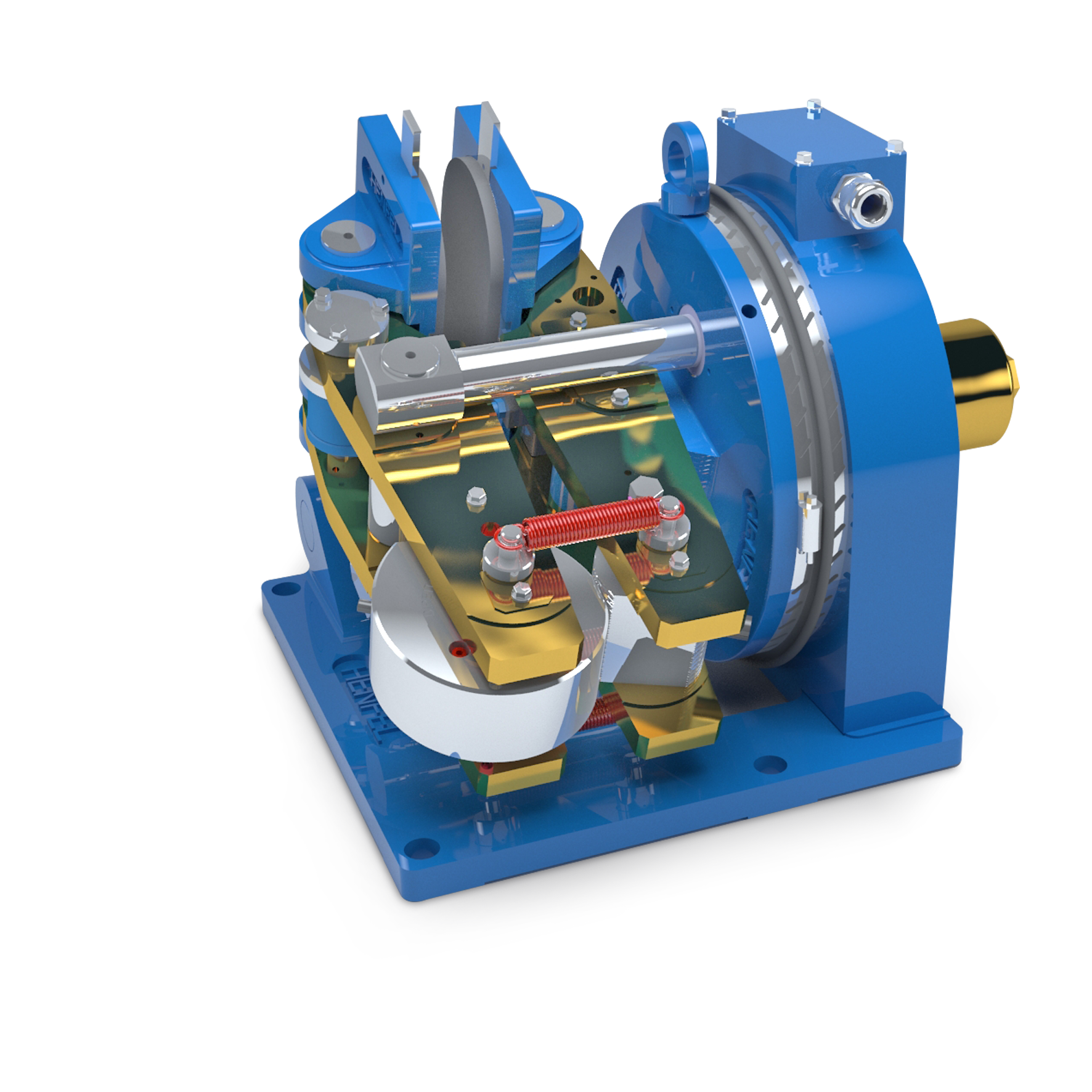
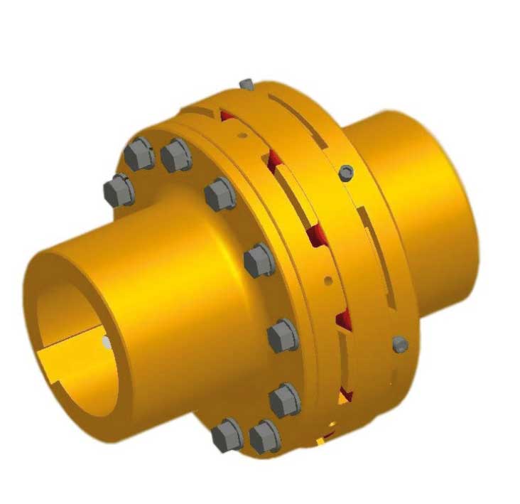
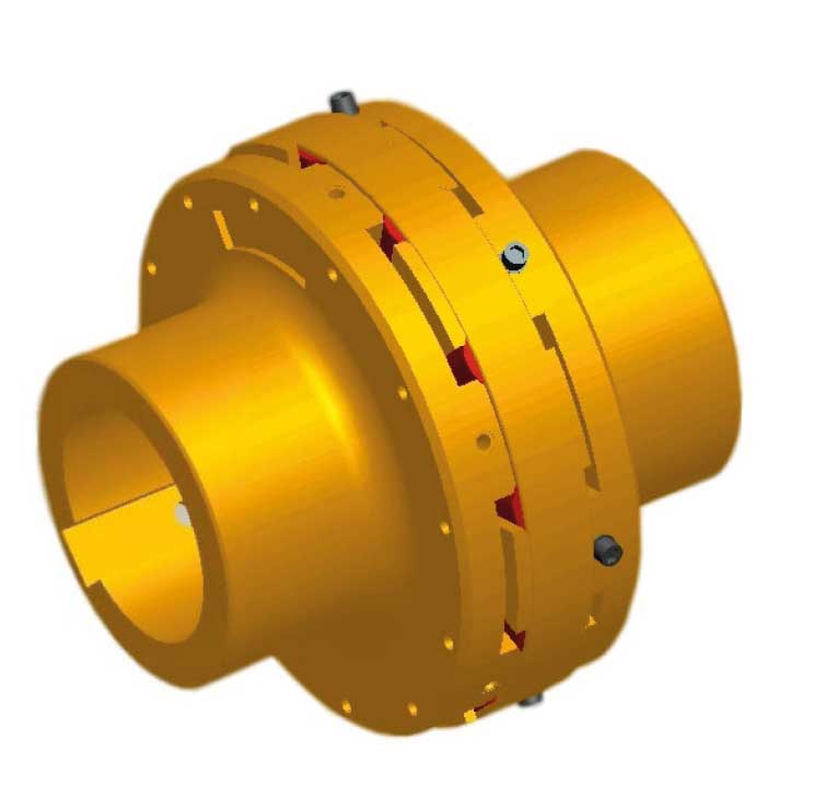
Developed considering the most up to date application engineering concepts and highly advanced 3D project techniques, these couplings provide efficient torque transmission through the compression of the elastic elements. These elastic elements also absorb vibrations and shocks coming from both the driving and driven machines and they compensate angular, radial and axial misalignments
Composed by ductile iron parts and polyurethane elastic elements resistant to the most aggressive environments, they can be applied in places with temperatures ranging between -30ºC and 85º C. Also, the ease of installation and maintenance simplicity are characteristics that complement the feasibility of this line
The Henflex HDF Flexible Couplings are available in many sizes, for shaft diameters between 25 and 600mm, with load capacities of up to 1.417.600 Nm. In order to attend a wide range of applications and project needs, 5 different constructive forms with interchangeable elements were designed
For greater values, HENFEL’s engineering department must be consulted.
First of all, define the operational torque given by the equation bellow
T0 = CxP/nm
Where:
T0 = System’s operational torque [Nm];
P = Input power [kW or HP]];
nm= Rotational speed [rpm]
C:
C = 9550 for Power in kW;
C = 7030 for power in HP.
From the operational torque, the coupling’s nominal torque is obtained (Tna), which is found in the following equation :
Tna ≥ T0 x f1
Where:
Tna = Coupling’s nominal torque;;
f1 = Service factor (See table bellow).
The service factor is a number obtained empirically that takes into account the operating regimes of the driving and driven machines.
The table bellow indicates the service factor considering the driven machine regimen and the drive type. In order to simplify the service conditions they were divided into three groups:
1. With uniform load;
2. With medium shocks;
3. With strong shocks
With the f1established, it is possible to determine the value of Tna. By checking the dimensional table, it is possible to select a suitable size for the torque range of the application.
The selection methods presented above are only valid if the environmental temperature where the coupling is applied ranges between -30ºC and 85ºC, with assembling and alignment as shown on the manual, with no more than 20 start ups per hour.
For more demanding applications or if you have any questions, please contact our engineering department
It’s also important to consider the shaft dimensions of the driving and driven machines as well as the admissible rotation speed of the couplings.
|
Service factors f1 |
||||
|
Type of loads* |
Type of loads* |
|||
|
Electric motor |
Internal combustion motor |
Internal combustion motor |
||
|
Uniform load |
- Fans P/n=0,1 - Centrifuge pumps (low viscosity) - Screw pumps - Electric generators |
2.0 |
2.4 |
2.6 |
|
Medium shocks |
- Blowers and fans P/n>0,1 - Belt and chain conveyors - Bucket elevators - Cranes - Shakers, centrifuges and mixers - Concrete mixers - Washing machines - Wood working machines - Plastic calenders, extrusors and mixers - Metal working machines - Metal planing machines - Marine propellers - Cylinders and Rotary kilns |
2.2 |
2.8 |
3.2 |
|
Strong shocks |
- Generators and transformers - Piston pumps - Mills - Brakers - Moendas - Sugar cane crushing equipment - Defibrator - Sugarcane appron feeder - Cylinders and Rotary kilns - Paper machines e celulose - Cranes - Bucket Wheel excavators - Presses, hammers and shears - Metal rolling mills equipments - Rubber mills and extruders - Elevators |
2.6 |
3.5 |
4 |
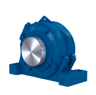
Used in applications with small gap between the shafts of the driving and driven machines.
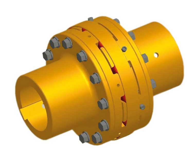
It’s composed by a hub with jaws, an additional hub, a flange with jaws and elastic elements radially assembled between the jaws. It’s possible to remove the driving and driven machines radially, and it’s not necessary to move them in order to replace the elastic elements.
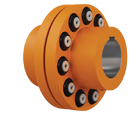
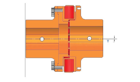
Basic coupling, composed by two equal hubs with jaws, with elastic elements radially assembled between them. It’s used in applications where the gap between the shafts of the driving and driven machines are small. It’s not possible to remove the hubs radially, however, it’s possible to replace the elastic elements without the need to displace the hubs.
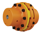
his model is derived from the HDF constructive form. Consists of two hubs, two flanges with jaws, and elastic elements assembled radially between the jaws.
It’s possible to remove the driving and driven machines radially, and it’s not necessary to displace them in order to replace the elastic elements..
One of the greatest advantages of this model is that in case of an accident that causes damage to the jaws, it’s possible to replace the flanges with jaws without removing the hubs that are assembled on the shafts of the driving and driven machines.
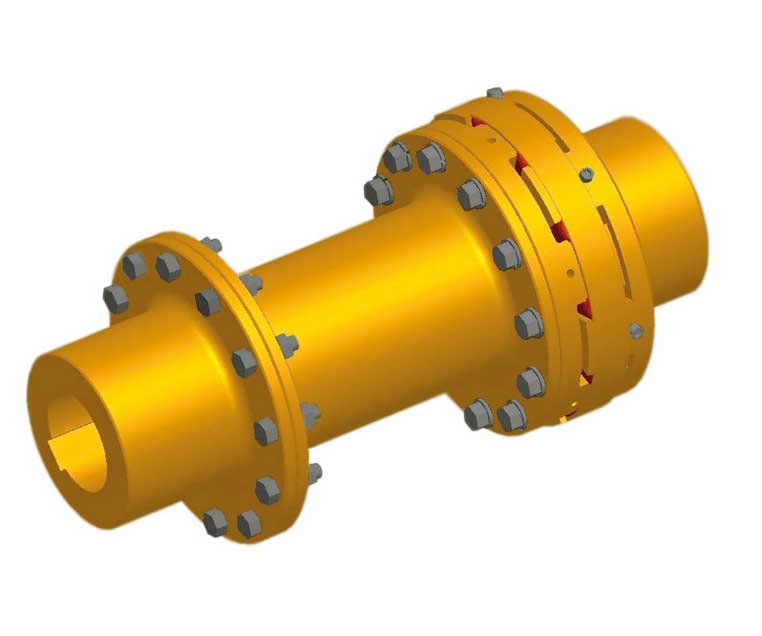
This model is derived from the HDF constructive form and it’s indicated for applications that require a larger gap than the ones from the HDF and HDFF models. It’s pretty similar to the HDF model, except for the radially removable spacer tube.
It’s possible to remove the driving and driven machines radially, and it’s not necessary to displace them in order to replace the elastic elements.
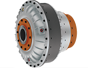
This model is derived from the HDF constructive form, with the inclusion of a brake disc. It’s possible to remove the driving and driven machines radially, and it’s not necessary to displace them in order to replace the elastic elements or the brake disc.
The HDF couplings are set on the shaft by a feather key in accordance with the norm DIN6885 part 1
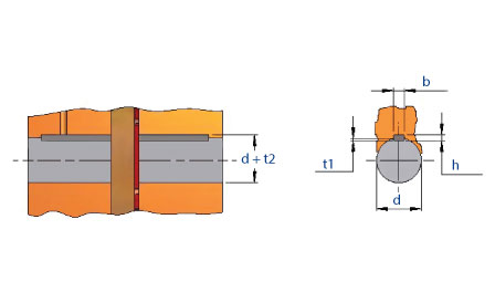
|
Feather Key – DIN 6885/1 |
|||||
|
Diameter d |
Width b(*) |
height h |
Keyway depth on the shaft t1 |
Keyway depth on the hub d + t2 |
|
|
Above of (mm) |
Until (mm) |
(mm) |
(mm) |
(mm) |
(mm) |
|
8 |
10 |
3 |
3 |
1,8 |
d+ 1,4 |
|
10 |
12 |
4 |
4 |
2,5 |
d+ 1,8 |
|
12 |
17 |
5 |
5 |
3 |
d+ 2,3 |
|
17 |
22 |
6 |
6 |
3,5 |
d+ 2,8 |
|
22 |
30 |
8 |
7 |
4 |
d+ 3,3 |
|
30 |
38 |
10 |
8 |
5 |
d+ 3,3 |
|
38 |
44 |
12 |
8 |
5 |
d+ 3,3 |
|
44 |
50 |
14 |
9 |
5,5 |
d+ 3,8 |
|
50 |
58 |
16 |
10 |
6 |
d+ 4,3 |
|
58 |
65 |
18 |
11 |
7 |
d+ 4,4 |
|
65 |
75 |
20 |
12 |
7,5 |
d+ 4,9 |
|
75 |
85 |
22 |
14 |
9 |
d+ 5,4 |
|
85 |
95 |
25 |
14 |
9 |
d+ 5,4 |
|
95 |
110 |
28 |
16 |
10 |
d+ 6,4 |
|
110 |
130 |
32 |
18 |
11 |
d+ 7,4 |
|
130 |
150 |
36 |
20 |
12 |
d+ 8,4 |
|
150 |
170 |
40 |
22 |
13 |
d+ 9,4 |
|
170 |
200 |
45 |
25 |
15 |
d+10,4 |
|
200 |
230 |
50 |
28 |
17 |
d+11,4 |
|
230 |
260 |
56 |
32 |
20 |
d+12,4 |
|
260 |
290 |
63 |
32 |
20 |
d+12,4 |
|
290 |
330 |
70 |
36 |
22 |
d+14,4 |
|
330 |
380 |
80 |
40 |
25 |
d+15,4 |
|
380 |
440 |
90 |
45 |
28 |
d+17,4 |
|
440 |
500 |
100 |
50 |
31 |
d+19,4 |
(*) The tolerance zone for the width “b” of the hub keyway is in accordance with the norms ISO JS9 or ISO P9 for severe operation conditions. (Eg. Loaded reversion)
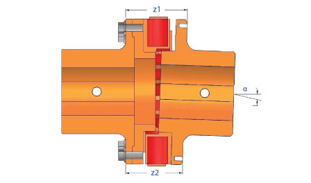

|
HDF Admissible misalignments table |
|||||||||||||||
|
Misalignment |
220 |
270 |
330 |
380 |
430 |
480 |
540 |
590 |
640 |
690 |
750 |
850 |
950 |
1050 |
1250 |
|
Axial ± x (mm) |
0,5 |
0,5 |
0,5 |
0,5 |
0,5 |
0,5 |
0,5 |
0,5 |
0,5 |
0,5 |
0,5 |
0,5 |
0,5 |
0,5 |
0,5 |
|
Radial y (mm) |
0,5 |
0,5 |
0,5 |
0,5 |
0,5 |
0,5 |
0,5 |
0,5 |
0,5 |
0,5 |
0,5 |
0,5 |
0,5 |
0,5 |
0,5 |
|
Angular (°) |
0,5 |
0,5 |
0,5 |
0,4 |
0,4 |
0,35 |
0,35 |
0,3 |
0,3 |
0,3 |
0,3 |
0,25 |
0,23 |
0,25 |
0,25 |
|
∆Z = Z1-Z2 (mm) |
2 |
2 |
2,5 |
2,5 |
2,75 |
2,75 |
3 |
3 |
3 |
3,25 |
3,5 |
3,5 |
3,5 |
4 |
5 |
|
Maximum Torsion Angle for HDF Couplings |
||||||||||||||||
|
Maximum Torsion Angle for HDF Couplings |
220 |
270 |
330 |
380 |
430 |
480 |
540 |
590 |
640 |
690 |
750 |
850 |
950 |
1050 |
1250 |
|
|
δ |
1/3 Mmax |
1,2 |
1,55 |
0,87 |
0,96 |
0,96 |
0,83 |
0,88 |
0,78 |
0,71 |
0,56 |
0,51 |
0,43 |
0,3 |
0,5 |
0,4 |
|
(o) |
Mmax |
2,1 |
2,54 |
1,75 |
2,08 |
2,08 |
1,8 |
1,93 |
1,72 |
1,55 |
1,25 |
1,17 |
0,99 |
0,8 |
1,1 |
1 |